In modern injection molding and tooling environments, manufacturers often face the challenge of reproducing legacy parts, replacing worn components, or adapting existing designs without access to original CAD data. Reverse Engineering combined with 3D scanning provides a structured pathway to convert a physical product into a digital CAD model that is ready for mold design and manufacturing. This approach reduces downtime, accelerates tooling development, and minimizes costly design iterations.
Reverse Engineering: When and Why We Use It
Reverse Engineering is the process of analyzing a physical part to reconstruct its geometry and design intent. It is typically applied in scenarios such as:
· Legacy parts: When original drawings or CAD files are missing, yet spare parts are required.
· Obsolete tooling: Reproducing components for equipment that is no longer supported by OEMs.
· Redesign opportunities: Improving manufacturability, performance, or adapting a part to new assembly requirements.
In injection molding, reverse engineering ensures continuity of production while enabling re-design for better moldability and reduced cycle times.
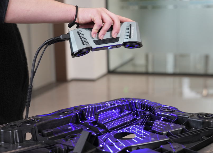
The Workflow: From 3D Scanning to Solid CAD
1. Data Capture (Point Cloud Acquisition)
Using 3D scanning technologies—laser scanners, structured light, or portable arms—millions of surface points are captured to form a point cloud. Accuracy at this stage directly impacts the fidelity of the final CAD model.
2. Mesh Generation
The point cloud is processed into a polygonal mesh. This involves noise reduction, hole filling, and mesh optimization. A clean mesh ensures smoother conversion into parametric surfaces.
3. Conversion to Solid CAD
Specialized software reconstructs surfaces and features from the mesh, creating a solid CAD model. Unlike a static mesh, a parametric CAD file allows engineers to adjust wall thickness, apply draft angles, and integrate mold-specific features. This step bridges the gap between raw scan data and a fully editable design suitable for tooling.
Tools and Software in Practice
Several hardware and software solutions dominate industrial reverse engineering:
· FARO scanners (e.g., FaroArm, Faro Focus) are widely used for high-precision industrial scanning, offering portability and accuracy for shop-floor applications.
· Geomagic Design X is a leading software for converting scan data into parametric CAD, enabling seamless integration with platforms like SolidWorks or Siemens NX.
The combination of robust scanning hardware and advanced CAD reconstruction software can reduce the conversion cycle by more than 50% compared to manual measurement and modeling workflows【sources: Faro, Geomagic】.
Design for Manufacturability (DFM) Considerations
Integrating DFM principles during reverse engineering ensures that the reconstructed CAD model is not only geometrically accurate but also optimized for molding. Adjustments such as draft angles, uniform wall thickness, and gate placement can be incorporated early. Studies indicate that applying DFM at the CAD stage can save up to 40% of downstream mold modification costs【sources: industry reports on DFM】.
For example, a scanned part with inconsistent wall thickness can be redesigned to improve cooling efficiency and reduce cycle time, directly impacting production economics.
Conclusion: Turning Physical into Digital Value
By combining Reverse Engineering, 3D scanning, and CAD modeling, manufacturers gain a powerful methodology to transform physical products into digital assets ready for mold design. The benefits are clear: reduced downtime, lower tooling costs, and the ability to re-design parts for improved manufacturability.
In practice, this workflow ensures that every physical component can be digitized, analyzed, and optimized—turning lost design data into a competitive advantage for modern injection molding operations.